25+ verilog code to block diagram converter
For now I am using ironPython to draw the block diagram in Visio. These tools can import verilog or vhdl.

Clock Domain Crossing Design Part 2 Verilog Pro
If your HDL design is in large part structural it may be easier for you to enter its description.

. Verilog Code To Block Diagram Converter - Read Verilog Code To Block Diagram Converter PDF on. Subscribe to RSS Feed. You can open the.
Despite that verilog seems to dominate the market and if I want to use open source toolchains my only option seems to be verilog. Convert verilog code to block diagram. Moreover on block design screen you can add remove rename modules and ports and generate top module code.
Verilog Code To Block Diagram Converter - PDF-10VCTBDC1 22 e-Book Name. Verilog code to block diagram. It converts a serial 2400 baud signal into a parallel signal.
Create a graph which matches all the outputs of a block. Here is the Verilog code. Mark Topic as New.
The renoir tool even the demo version creates a work directory and stores the graphical data there. Saving when going from code to graphics is not needed. Ive been trying to convert this Mealy finite state machine into Verilog code and it never manages to work for all combinations of statesinputsetc.
Summit can do it. Seeing that youre using a Lite version of Quartus maybe you dont actually are interested in Altera synthesis but more in general Verilog analysis and clever code optimization. This converter may help if just the serial port on a personal computer is free whereas the printer needs a parallel Centronics port.
I am looking for a way to generate the block design from the existing Verilog and IP because even though I am able to synthesize the project run implementation and generate a. Verilog code to block diagram. The Block Diagram Editor is a tool for graphical entry of VHDL Verilog and EDIF designs.
I dont think I even have much access to SystemVerilog in. Create a list of blocks with their inputs and outputs. You can create a Symbol File with your verilog file open click File-CreateSymbol File associated to your verilog module so you can use it as a block in your block schematic.
I think you can have a try for the fpga advantage of Mentor or the active-hdl of aldec. This GUI converts Verilog top module code into a block design. Or you can try hds of mentor.

Clock Domain Crossing Design 3 Part Series Verilog Pro
Verilog Twins Case Casez Casex Verilog Pro

Full Vhdl Code For Moore Fsm Sequence Detector Coding Detector Sequencing

Clock Domain Crossing Design Part 2 Verilog Pro
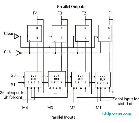
Universal Shift Register Design Working Its Applications
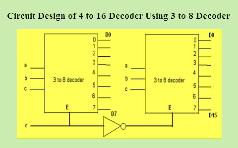
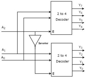
How To Design A 4 To 16 Decoder Using 3 To 8 Decoder

Dual Clock Asynchronous Fifo In Systemverilog Verilog Pro
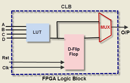
Know About Fpga Architecture And Thier Applications
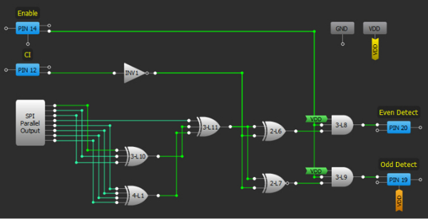
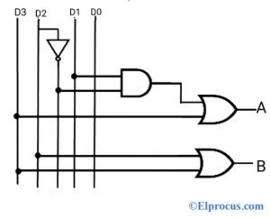
Parity Generator And Parity Checker Logic Circuits And Their Types
3 To 8 Line Decoder Designing Steps Its Applications

Clock Domain Crossing Design Part 2 Verilog Pro

Dual Clock Asynchronous Fifo In Systemverilog Verilog Pro
Priority Encoder Truth Table Verilog Code Its Applications
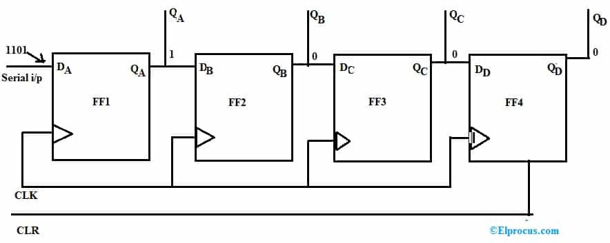
Sipo Shift Register Circuit Working Truth Table Its Applications

Full Verilog Code For Moore Fsm Sequence Detector Coding Detector Sequencing

Matrix Multiplication Xilinx Fpga Vhdl Verilog Turorials Matrix Multiplication Matrix Coding

8251 Is A Usart For Serialdatacommunication As A Peripheral Device Of A Microcomputer System The 8251 Receives Paralle Block Diagram Reading Writing Modem